
Black Friday VIP Hour Limited Time 75% Discount Offer - Ends in 0d 00h 00m 00s - Coupon code = simple75
Pass the HP ACA Campus Access Associate HPE6-A85 Questions and answers with Dumpstech
Which action explains how to carry out a hard reset on a switch?
Options:
Press and hold the Reset button for exactly two seconds, then release it immediately.
Press and hold the Reset button for more than five seconds, then release it.
Hold the Reset button while turning the switch on to trigger the reset process.
Press and release the Reset button quickly and wait for the switch to restart.
Comprehensive and Detailed Explanation
HPE Press guide context | PDF page 1008 | HPE Press, Aruba Certified Associate – Campus Access Official Certification Study Guide
Technical Deep Dive — Original Chat Wording
A hard reset forces a network switch to restart in a manner comparable to cycling its power.
It is particularly useful when the switch has become unresponsive and cannot be rebooted through the ordinary operating-system interface.
On supported AOS-CX switches, the Reset button is recessed to reduce the likelihood of accidental activation.
An administrator can use a suitable pointed tool to operate it.
The duration for which the button remains pressed determines the reset operation.
Soft reset: Release before 5 seconds
Hard reset: Release between 5 and 20 seconds
Factory reset: Release between 20 and 25 seconds, where enabled
A soft reset attempts a controlled system restart.
A hard reset performs a more forceful restart, which may be appropriate when the CPU or operating system is not responding.
A factory reset is different because it can remove the switch's configuration and restore factory-default operation.
Therefore, engineers must avoid holding the Reset button longer than necessary.
A hard reset interrupts forwarding while the switch restarts and should be performed only when operationally appropriate.
The original answer states only that the button should be held for more than five seconds. For technical accuracy, the release should occur before 20 seconds .
Therefore, Option B is correct, subject to that timing requirement.
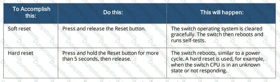
HPE Press study-guide figure / related learning illustration · Q147 Fig 13-13 Reset
Which statement is correct for a device whose MAC address is BB-31-B5-80-41-4F?
Options:
The device OUI is BB-31-B5 and the device NIC serial number is 80-41-4F
The device OUI is B8-31 and the device NIC serial number is B5-80-41-4F
The device OUI is B8-31-B5 and the device serial number is MD 5 hash is 80-41-4F
The device OUI is 80-41-4F and the device NIC serial number is B8-31-B5
Comprehensive and Detailed Explanation
HPE Press guide context | PDF page 49 | HPE Press, Aruba Certified Associate – Campus Access Official Certification Study Guide
Technical Deep Dive — Reconstructed (Original Chat Text Not Recoverable)
An Ethernet MAC address conventionally comprises a three-octet organizational prefix and a three-octet device identifier. The choice splitting BB-31-B5 from 80-41-4F follows that conventional pattern. However, the displayed leading octet BB has the locally administered bit set, so treating this as an IEEE-assigned globally unique OUI is technically questionable.
The selected answer corresponds to A: The device OUI is BB-31-B5 and the device NIC serial number is 80-41-4F. This matches the mechanism or management behavior described in the scenario rather than merely a related network feature.
Operational workflows should preserve consistent inventory, authorization, configuration history, and monitoring so that administrators can locate and manage devices predictably.
The operational view should be interpreted together with its underlying records: an alert, subscription count, or device status may describe management state rather than physical availability.
Technical validation: this item contains a qualification or possible source-version ambiguity. Do not treat the choice as an unrestricted universal rule; retain the original exhibit and compare the exact deployment context with the relevant HPE documentation.
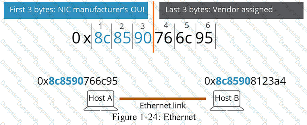
HPE Press study-guide figure / related learning illustration · Q67 Ethernet MAC
What action should you take after resolving an issue that triggered a network alert?
Options:
Acknowledge the alert in the monitoring system.
Defer the alert to review it later.
Clear the alert from the active alerts list.
Set the alert to a lower priority level.
Comprehensive and Detailed Explanation
HPE Press guide context | PDF page 1028 | HPE Press, Aruba Certified Associate – Campus Access Official Certification Study Guide
Technical Deep Dive — Original Chat Wording
An alert indicates that a monitored network condition has met the criteria for administrative attention.
After investigating and resolving the underlying problem, the administrator should confirm that normal operation has been restored.
For example, if an AP-disconnection alert was caused by a failed switch port, the technician should verify that the AP reconnects and that client connectivity has recovered.
Acknowledgment allows the administrator to mark the reported alert as reviewed.
In the documented Central interface, acknowledged alerts move to a separate view, preserving their history while removing them from the normal open-alert workflow.
However, acknowledging an alert does not independently repair the network.
If the underlying condition remains active, the monitoring system may continue collecting events and generating notifications according to its configured behavior.
Some alerts are automatically acknowledged when their triggering conditions clear.
Consequently, a technician should avoid manually dismissing alerts without confirming that the associated fault has been resolved.
Deferral postpones attention and is inappropriate when the issue has already been corrected.
Reducing priority changes the alert's urgency but does not establish closure.
The documented operator action that best matches the question is acknowledgment.
Therefore, Option A (Acknowledge the alert in the monitoring system) is correct.
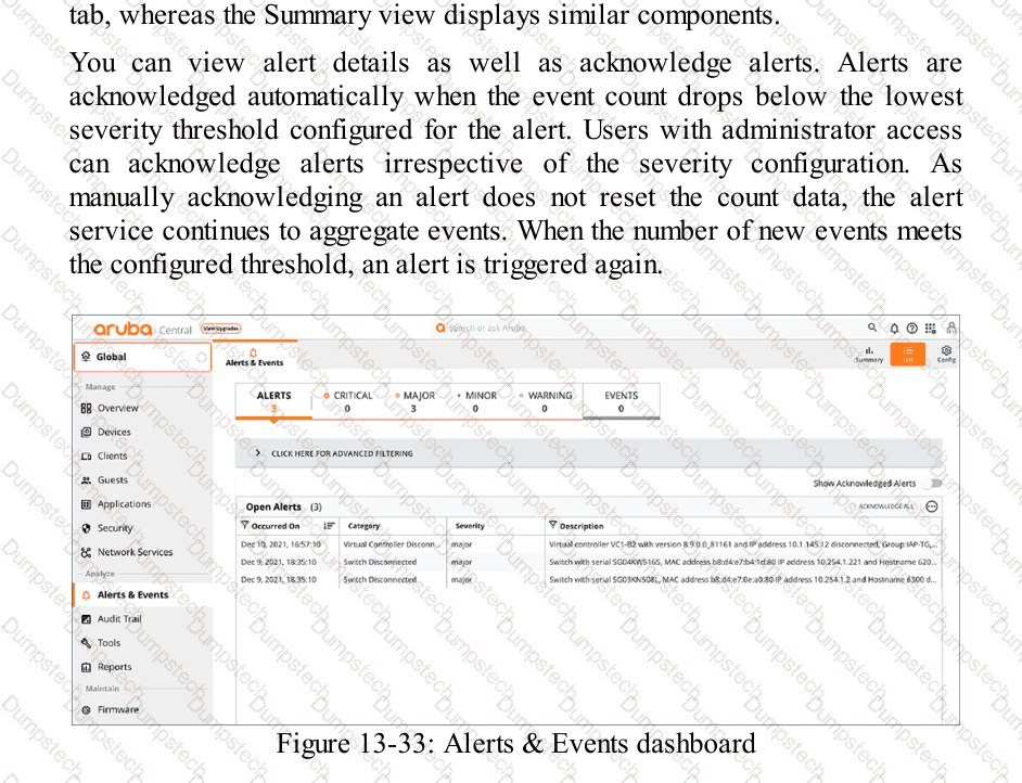
HPE Press study-guide figure / related learning illustration · Q176 Fig 13-33 Alerts
Which statement concerning Dynamic Frequency Selection (DFS) Wi-Fi channels is accurate?
Options:
DFS channels are only present on the 5GHz spectrum.
DFS channels should be included in all wireless designs.
DFS channels are required to use channel bonding.
DFS channels should not be used in very-high-density (VHD) systems.
Comprehensive and Detailed Explanation
HPE Press guide context | PDF page 709 | HPE Press, Aruba Certified Associate – Campus Access Official Certification Study Guide
Technical Deep Dive — Original Chat Wording
Dynamic Frequency Selection (DFS) is a regulatory spectrum-sharing mechanism used with designated Wi-Fi channels in the 5 GHz band.
Its purpose is to protect radar systems operating in portions of the same radio spectrum.
When an AP uses a DFS channel, it must satisfy applicable radar-detection requirements.
Before transmitting on certain DFS channels, the AP may need to perform a Channel Availability Check (CAC).
If radar activity is detected, the AP must vacate the affected channel according to the applicable regulatory rules.
This can result in channel changes and temporary connectivity disruption.
However, DFS channels also provide additional spectrum that may reduce co-channel interference in crowded WLAN environments.
Consequently, DFS should not be universally enabled or universally excluded without considering the deployment's regulatory region, radar exposure, client support, and availability requirements.
DFS is not required merely to configure 40 MHz or 80 MHz channel bonding.
Channel bonding can use appropriate non-DFS channels where permitted.
The 2.4 GHz band does not use the 5 GHz Wi-Fi DFS mechanism, and 6 GHz Wi-Fi operation has different spectrum-sharing requirements, including Automatic Frequency Coordination for certain operating classes.
Therefore, among the listed choices, Option A is correct.
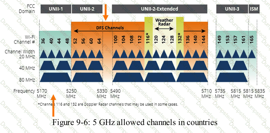
HPE Press study-guide figure / related learning illustration · Q125 Fig 9-6 DFS
What results from establishing goals at the beginning of a network design project?
Options:
It helps define the scope of work for the project.
It sets the technical specifications for all network components.
It identifies which vendor partners will be involved in deployment.
It helps determine the hardware requirements for the network project.
Comprehensive and Detailed Explanation
HPE Press guide context | PDF page 567 | HPE Press, Aruba Certified Associate – Campus Access Official Certification Study Guide
Technical Deep Dive — Original Chat Wording
Establishing project goals is one of the first activities in designing a campus network.
Project goals describe the outcomes that the organization expects from the proposed solution.
Examples include improving wireless coverage, increasing network availability, providing secure guest access, or expanding capacity for future devices.
These objectives determine the boundaries of the project and help establish what must be delivered.
For example, an organization may define a goal of providing reliable wireless connectivity across three office buildings.
This objective helps the project team determine whether the work includes wireless surveys, access-point installation, switch upgrades, authentication integration, and ongoing management configuration.
The resulting scope of work defines the activities and deliverables required to satisfy the agreed objectives.
Technical specifications are developed later after requirements have been analyzed.
Hardware selection depends on factors such as port density, PoE demand, bandwidth, availability, and expected growth.
Vendor selection is also a subsequent decision that may depend on procurement and technical requirements.
Defining goals does not independently determine every switch model or interface specification.
It provides the basis for making those decisions consistently.
Therefore, Option A (It helps define the scope of work for the project) is correct.
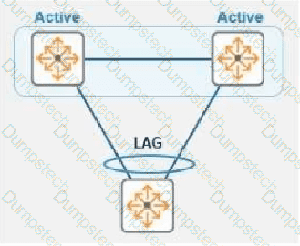
Refer to the exhibit.
In this topology, two CX 8325 switches form a VSX stack using the active gateway. What is the nature and behavior of the Virtual IP for the VSX pair when clients connect to the access switch and use VSX as their default gateway?
Options:
Virtual floating IP will failover in case of a failure
Virtual IP is active on both CX switches
Virtual IP uses SVI IP address synced with VSX
Virtual IP is active on the primary VSX switch
Comprehensive and Detailed Explanation
HPE Press guide context | PDF page 416 | HPE Press, Aruba Certified Associate – Campus Access Official Certification Study Guide
Technical Deep Dive — Reconstructed (Original Chat Text Not Recoverable)
VSX active gateway operates simultaneously on both peers with the same virtual gateway IP and virtual MAC. Client traffic can be routed locally by either peer and need not rely on a single floating master gateway. This is an active/active forwarding design, unlike conventional VRRP Master/Backup behavior.
The selected answer corresponds to B: Virtual IP is active on both CX switches. This matches the mechanism or management behavior described in the scenario rather than merely a related network feature.
A disciplined investigation compares the observed symptom with expected behavior, tests the most likely failure stage, and verifies recovery rather than assuming that a single command has resolved the problem.
When possible, test the affected and unaffected paths in parallel; the differences often identify the precise dependency that is failing.
For an administrator preparing for the associate certification, the key distinction is the precise protocol or Central workflow involved. Similar-sounding features often operate at different OSI layers or management stages.
Which fiber connector is used most commonly for AOS-CX switches?
Options:
SC
LC/APC
LC
ST
Comprehensive and Detailed Explanation
HPE Press guide context | PDF page 42 | HPE Press, Aruba Certified Associate – Campus Access Official Certification Study Guide
Technical Deep Dive — Reconstructed (Original Chat Text Not Recoverable)
LC (Lucent Connector) is the compact optical connector commonly used by SFP and QSFP breakout fiber interfaces in campus switches. LC/APC has an angled polish and is not the ordinary switch transceiver connector. SC and ST exist in legacy fiber deployments, but LC is the standard connector for the optics highlighted in the HPE Press guide.
The selected answer corresponds to C: LC. This matches the mechanism or management behavior described in the scenario rather than merely a related network feature.
Operational workflows should preserve consistent inventory, authorization, configuration history, and monitoring so that administrators can locate and manage devices predictably.
The operational view should be interpreted together with its underlying records: an alert, subscription count, or device status may describe management state rather than physical availability.
The practical deployment consequence is important: a plausible configuration can still fail when the peer interface, device role, licensing scope, or physical medium is mismatched. Checking that surrounding dependency avoids a misleading diagnosis.
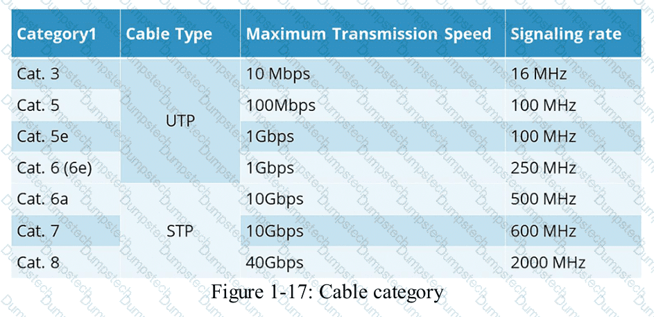
HPE Press study-guide figure / related learning illustration · Q132 Fig 1-17 Cable Cat
Which design information should be reviewed before troubleshooting a wired network?
Options:
The settings for each port on the connected switches
The rack locations for all power supply equipment
The network cable colors used throughout the building
The locations of wiring closets and network rooms
Comprehensive and Detailed Explanation
HPE Press guide context | PDF page 40 | HPE Press, Aruba Certified Associate – Campus Access Official Certification Study Guide
Technical Deep Dive — Original Chat Wording
Wired-network troubleshooting begins with understanding the physical and logical architecture of the deployed network.
Physical design documentation identifies the locations of network rooms, wiring closets, patch panels, switches, and cabling routes.
This information is important because a connectivity failure may originate from a physical infrastructure problem rather than an incorrect device configuration.
For example, when several office workstations simultaneously lose connectivity, knowing their associated wiring closet helps a technician identify a possible shared access-switch or uplink failure.
The technician can then trace connectivity from affected endpoints through their patch-panel connections to the serving switch.
Accurate location information also helps technicians determine whether a cable run exceeds supported Ethernet distance limits.
In structured copper Ethernet deployments, a standard channel commonly supports a maximum length of 100 meters, subject to the applicable cabling and Ethernet standard.
Switch-port settings are important during troubleshooting, especially when investigating VLANs, interface status, or authentication failures.
However, Option A describes detailed configuration information rather than the physical network-design information targeted by the question.
Power equipment locations and cable colors can provide supporting information but do not replace a physical connectivity map.
Therefore, Option D (The locations of wiring closets and network rooms) is the best answer.
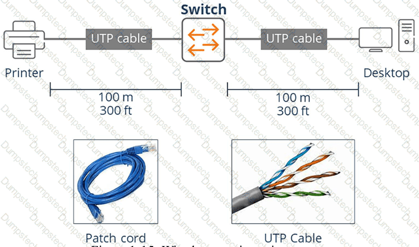
HPE Press study-guide figure / related learning illustration · Q161 Fig 1-15 Copper
Which statement describes alerts in HPE Aruba Networking Central?
Options:
Alerts are displayed only on dashboards
Alerts summarize historical performance trends
Alerts display device status in real time
Administrators can set thresholds for triggering alerts
Comprehensive and Detailed Explanation
HPE Press guide context | PDF page 1028 | HPE Press, Aruba Certified Associate – Campus Access Official Certification Study Guide
Technical Deep Dive — Original Chat Wording
HPE Aruba Networking Central provides alerting to notify administrators when monitored infrastructure conditions require attention.
An alert is generally triggered when a specific event or measured condition meets the configured criteria.
For example, an administrator may configure an AP-disconnection alert with an evaluation duration so that a brief interruption does not immediately generate an operational incident.
Depending on the alert type, administrators may be able to configure severity, duration, applicable devices, and notification recipients.
Thresholds help distinguish significant problems from ordinary fluctuations.
This reduces unnecessary notifications and improves the effectiveness of network monitoring.
Alerts can be presented within dashboards, event lists, and supported notification channels.
Therefore, they are not limited exclusively to dashboard displays.
Historical performance reporting is a separate function that summarizes trends over time.
Likewise, real-time device status is normally represented through infrastructure-health and device-monitoring views.
Alerts may report conditions derived from device status, but they are event-driven notifications rather than simply a continuously updated device-status display.
Administrators should configure alert thresholds according to business impact and expected operational behavior.
Excessively sensitive thresholds can produce alert fatigue, while poorly chosen thresholds may delay detection of significant failures.
Therefore, Option D (Administrators can set thresholds for triggering alerts) is correct.
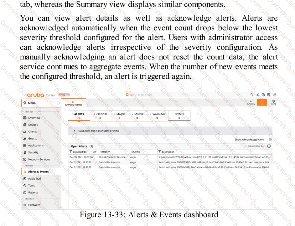
HPE Press study-guide figure / related learning illustration · Q174 Fig 13-33 Alerts
How do real-time alerts in HPE Aruba Networking Central assist you in troubleshooting critical network events?
Options:
They monitor general network health metrics for long-term performance optimization
They send notifications about important issues so you can quickly respond
They show summarized reports after network problems have already been resolved
They collect and archive logs for future audit and regulatory compliance review
Comprehensive and Detailed Explanation
HPE Press guide context | PDF page 1028 | HPE Press, Aruba Certified Associate – Campus Access Official Certification Study Guide
Technical Deep Dive — Original Chat Wording
Real-time alerting enables network administrators to identify and respond to operational problems before they cause prolonged service disruption.
HPE Aruba Networking Central continuously monitors supported network infrastructure and can generate alerts when significant conditions occur.
Examples include access point disconnections, switch availability problems, authentication failures, connectivity degradation, and other network events.
When an alert condition is detected, Central records the corresponding event and can notify administrators through configured notification mechanisms.
The administrator can then examine relevant information, including affected devices, severity, event time, and associated operational details.
This provides an efficient starting point for troubleshooting.
For example, if several APs unexpectedly disconnect, Central can generate device-disconnection alerts.
A network technician can use these alerts to identify affected devices and investigate common infrastructure dependencies, such as PoE switches, uplinks, or management connectivity.
The alert acknowledgment feature allows administrators to record that an issue has been reviewed.
However, acknowledgment does not automatically resolve the underlying technical problem.
Long-term monitoring, historical reporting, and audit logging serve related but different purposes.
Real-time alerting is specifically intended to provide timely awareness of significant network conditions requiring attention.
Therefore, Option B is correct.
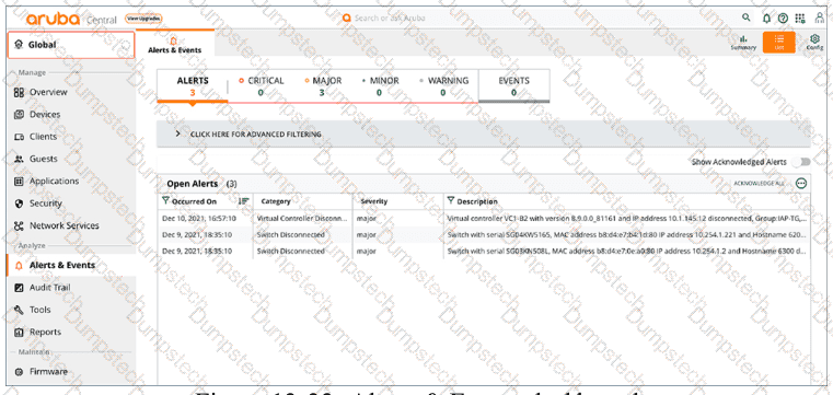
HPE Press study-guide figure / related learning illustration · Fig 13-33 Alerts
Modal title
